If you’ve ever unrolled a set of blueprints and felt your eyes glaze over at the maze of lines, arrows, and tiny numbers, you’re not alone — learning how to read architectural drawings is one of those skills that looks impossible right up until the moment it suddenly clicks. Once you understand the handful of core conventions every drawing set follows, a page that used to look like abstract art turns into a clear, logical instruction manual for an entire building.
This guide is built to get you there faster than the typical “here are some symbols” roundup. We’ll cover the building blocks every drawing set shares (title block, scale, north arrow, legend), how to actually read scale in both metric and imperial systems, what line weight is quietly telling you, the right order to work through a full drawing set, every major drawing type from site plans to reflected ceiling plans, a full symbol reference table, how drawing revisions work, and the most common mistakes beginners make. Whether you’re a homeowner reviewing plans for your own project or simply curious, this is the same foundation our team walks clients through before every build — you can see it applied in real projects across our architecture and design portfolio at Archtra.
Table of Contents
- Why Learning to Read Architectural Drawings Matters
- The Building Blocks: Title Block, Scale, North Arrow, and Legend
- Understanding Scale (Metric and Imperial)
- Line Weights: What Thick and Thin Lines Actually Mean
- The Right Order to Read a Full Drawing Set
- Types of Architectural Drawings Explained
- Common Architectural Drawing Symbols
- Understanding Drawing Revisions and Version Control
- Digital Drawings: PDFs, BIM, and 3D Models
- Common Mistakes When Reading Architectural Drawings
- Tips for Homeowners Reviewing Their Own House Plans
- Frequently Asked Questions
Why Learning to Read Architectural Drawings Matters
You don’t need a design degree to benefit from knowing how to read architectural drawings. Homeowners reviewing plans before a renovation, buyers evaluating a property, and even DIY-minded people planning a small project all run into the same wall of unfamiliar symbols and notation. Understanding the basics lets you catch mistakes early, ask sharper questions during a design review, and actually visualize a finished space before a single wall is built — which is exactly why this is one of the most valuable skills to pick up before starting any project, including working through our own guide to the custom home building process.
The Building Blocks: Title Block, Scale, North Arrow, and Legend
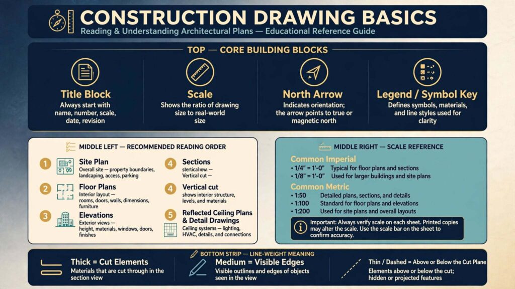
Every architectural drawing, regardless of type, is built around the same four reference points. Learning to check these first — before trying to interpret anything else — is the single fastest way to get oriented on any new drawing set.
- Title block — usually located in a bottom or side corner, this contains the drawing title (e.g., “Ground Floor Plan”), drawing number, scale, project name, date, and revision number. Always start here.
- Scale — tells you how a measurement on paper translates to real-world size. Never assume; scale can vary between pages in the same set.
- North arrow — indicates orientation, which matters enormously for understanding natural light, room placement, and how the building sits on its site.
- Legend/symbol key — decodes any symbols specific to that drawing set. Symbols aren’t perfectly universal across firms or countries, so the legend always overrides any general reference, including this guide.
Understanding Scale (Metric and Imperial)
Scale is what turns a page of lines into a precise, buildable instruction — without it, you’re just looking at a picture rather than a technical document. Both metric and imperial scale systems remain in active global use, so knowing both is genuinely useful when learning how to read architectural drawings from different regions.
Common imperial scales (used mainly in the U.S.):
- 1/4″ = 1′-0″ (a common scale for residential floor plans)
- 1/8″ = 1′-0″ (used for larger buildings or site plans)
- 3/4″ = 1′-0″ (used for detailed close-ups)
Common metric scales (used across most of the world, including the UK, Europe, Australia, and India):
- 1:50 (common for detailed floor plans)
- 1:100 (common for general floor plans and site layouts)
- 1:200 or 1:500 (used for larger site plans)
A quick way to think about it: at 1:100 scale, 1 centimeter on the drawing equals 1 meter in real life. Always double-check the scale noted in the title block rather than assuming it matches the previous page you looked at — mismatched scale assumptions are a surprisingly common source of measurement errors, even among experienced readers.
Line Weights: What Thick and Thin Lines Actually Mean
This is one of the most underexplained parts of learning how to read architectural drawings, even though it carries as much meaning as the symbols themselves. Line weight (thickness) isn’t decorative — it communicates depth and hierarchy:
- Thick, bold lines typically represent elements cut directly by the drawing’s viewing plane — for example, a wall sliced through at floor-plan height.
- Medium lines usually represent visible edges and objects within the space, like furniture outlines or cabinetry.
- Thin or dashed lines often represent elements above or below the current cut plane — a wall cabinet shown as dashed on a floor plan, for instance, or a beam overhead.
A wall drawn with a thin line generally isn’t a wall at all in that view — it’s something existing above or below the plane being shown, which is a distinction that trips up a lot of first-time readers.
The Right Order to Read a Full Drawing Set
Rather than jumping straight to the floor plan (a common instinct), professionals typically work through a drawing set in a specific sequence that builds understanding progressively:
- Site plan — establishes the building’s position, orientation, and relationship to the surrounding property.
- Floor plans — the horizontal layout of each level.
- Elevations — exterior views showing height, materials, and facade design.
- Sections — vertical “slices” through the building showing internal structure and ceiling heights.
- Reflected ceiling plans and detail drawings — the finer-grained information that ties everything together.
Following this order builds a mental 3D model of the building step by step, rather than trying to interpret isolated pages out of context — which is often why floor plans alone can feel confusing without the surrounding drawings for reference.
Types of Architectural Drawings Explained
Site Plan
A bird’s-eye view of the entire property, showing the building’s footprint, property lines, setbacks, driveways, and landscaping. This is the first drawing to check when evaluating how a building relates to its surrounding lot — a detail covered in more depth in our guide to choosing and evaluating a building lot.
Floor Plan
A horizontal “slice” through the building, typically cut around 1 to 1.5 meters above the floor, showing walls, doors, windows, room layout, and dimensions. It’s the most commonly referenced drawing type, and usually the first one most people learn to read.
Elevations
Straight-on exterior views of each face of the building (front, rear, and sides), showing height, roofline, window and door placement, and exterior material choices. Elevations are essential for understanding what a building will actually look like from the street or yard, something a floor plan alone can’t convey.
Sections
A vertical cut through the building, revealing interior structure, ceiling heights, stair configurations, and how different floor levels relate to each other. Sections are particularly useful for understanding multi-story homes or spaces with varied ceiling heights.
Reflected Ceiling Plan (RCP)
A less commonly explained drawing type that shows the ceiling as if you were looking at its reflection in a mirror on the floor — hence “reflected.” It maps lighting fixtures, ceiling height changes, and HVAC diffusers, and is essential for coordinating electrical and mechanical work, even though most beginner guides skip it entirely.
MEP Drawings (Mechanical, Electrical, Plumbing)
Separate drawing sheets dedicated to a building’s mechanical systems (heating/cooling), electrical wiring and outlet placement, and plumbing layout. These are typically reviewed by specialized contractors, but a basic understanding helps homeowners follow along during design and construction discussions.
Detail Drawings
Highly zoomed-in drawings of specific construction elements — a window frame connection, a stair railing, a foundation detail — drawn at a much larger scale to communicate exact construction methods that wouldn’t be legible at a floor-plan scale.
Common Architectural Drawing Symbols
While every drawing set includes its own legend (and you should always defer to it over any general reference), these symbols are consistent enough across most residential drawing sets to serve as a reliable starting vocabulary:
| Element | How It’s Typically Shown |
|---|---|
| Wall | A solid, filled or hatched line, thickness matching actual wall width |
| Door | A straight line with a quarter-circle arc showing swing direction |
| Window | A break in the wall line with parallel lines representing glazing |
| Stairs | Parallel lines with an arrow indicating the direction of travel (usually “up”) |
| Section marker | A circle or arrow with a line indicating where a section cut is taken |
| Centerline | A dash-dot-dash line marking the center of a symmetrical element, like a column |
| Electrical outlet | A small circle with two short marks, often labeled |
| North arrow | A directional arrow, usually near the site plan or floor plan, labeled “N” |
Understanding Drawing Revisions and Version Control
This is a practical detail almost no beginner guide covers, despite being critical to avoiding costly mistakes: architectural drawings are rarely finalized in a single pass. Every drawing set includes a revision log, typically in or near the title block, tracking each update with a revision number, date, and brief description of what changed.
Before reviewing or building from any drawing, always confirm you’re looking at the most current revision — working from an outdated version is one of the most common (and expensive) mistakes on real construction sites, and it’s just as easy to make as a homeowner reviewing plans at home.
Digital Drawings: PDFs, BIM, and 3D Models
Most architectural drawings today are distributed as digital PDFs rather than physical rolled prints, and increasingly generated from Building Information Modeling (BIM) software rather than traditional 2D drafting. A few practical implications worth knowing:
- Digital PDFs typically allow you to measure directly on-screen using built-in scale tools, which can be more accurate than eyeballing a printed ruler.
- BIM-based drawings are generated from a single coordinated 3D model, meaning floor plans, elevations, and sections stay automatically consistent with each other — reducing (though not eliminating) the coordination errors common in older, separately-drafted drawing sets.
- 3D walkthroughs and renderings, increasingly common alongside traditional drawings, can make spatial relationships far easier to understand for non-professionals than 2D plans alone, especially for complex, multi-level designs.
Common Mistakes When Reading Architectural Drawings
After reviewing the leading guides currently ranking for how to read architectural drawings, a few recurring beginner mistakes stand out that deserve more direct attention:
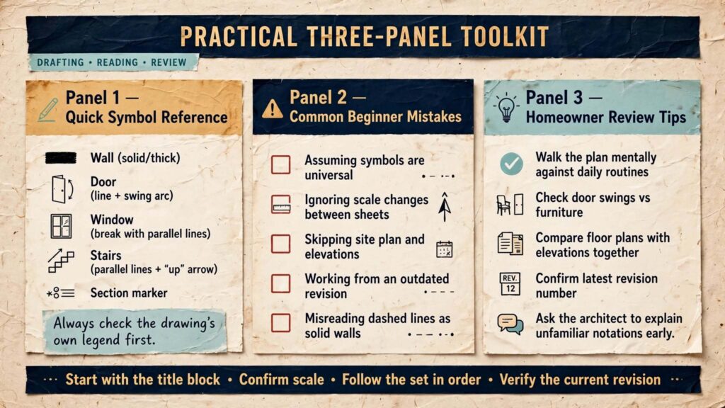
- Assuming symbols are universal. As covered above, symbols vary by firm, region, and even individual project — always check the legend first.
- Ignoring scale changes between pages. Not every sheet in a set is drawn at the same scale; always verify before measuring.
- Skipping the site plan and elevations. Reading only the floor plan gives an incomplete picture of how a space actually looks and functions in three dimensions.
- Working from an outdated revision. Always confirm the current revision number before relying on any measurement or detail.
- Misreading dashed lines as solid walls, or vice versa — a mistake that can lead to serious misunderstandings about what’s actually being built versus what’s simply shown for reference.
Tips for Homeowners Reviewing Their Own House Plans
If you’re learning how to read architectural drawings specifically to review plans for your own home, a few practical habits make the process far more productive:
- Walk the plan mentally, room by room, imagining your actual daily routine — getting ready in the morning, cooking dinner, hosting guests — to catch layout issues a purely visual review might miss.
- Check door swings against furniture placement before finalizing a layout; a door that swings into a planned closet or bed location is a common, easily missed conflict.
- Compare the floor plan against elevations together, rather than reviewing them separately, to build an accurate sense of how interior layout and exterior appearance relate.
- Ask your architect to walk through unfamiliar symbols or notations directly — a five-minute conversation early on can prevent a much larger misunderstanding later. If you’re still in the process of finding the right professional to guide you through this, our guide on how to choose an architect covers exactly what to look for.
Frequently Asked Questions
1. What is the first thing I should look at when reading an architectural drawing? Always start with the title block — it tells you the drawing’s title, scale, date, and revision number, all of which are essential context before interpreting anything else on the page.
2. What’s the difference between a floor plan and a site plan? A site plan shows the entire property from above, including the building’s position relative to property lines and landscaping. A floor plan is a closer, horizontal “slice” through the building itself, showing the layout of rooms, walls, doors, and windows.
3. Why do symbols look different between different sets of architectural drawings? Symbols aren’t fully standardized across firms, offices, or countries — each drawing set includes its own legend, which always takes precedence over any general symbol reference, including this guide.
4. How do I read the scale on an architectural drawing? Check the title block or the area directly below the specific drawing for the scale notation (such as 1:100 or 1/4″ = 1′-0″), then use a scale ruler, or a digital measuring tool if reviewing a PDF, to convert on-paper measurements to real-world dimensions.
5. What does a dashed line mean on a floor plan? Dashed lines typically represent elements above or below the plan’s cut height — for example, upper cabinets, a beam overhead, or a roofline visible from that vantage point — rather than a wall that actually exists at that floor level.
6. What is a reflected ceiling plan, and why does it matter? A reflected ceiling plan (RCP) shows the ceiling as though reflected onto the floor below, mapping lighting fixtures, ceiling height changes, and mechanical elements. It’s essential for coordinating electrical and HVAC work, even though it’s one of the least-explained drawing types in most beginner guides.
7. How do I know if I’m looking at the most current version of a drawing? Check the revision log, typically located in or near the title block, which lists each update by revision number and date. Always confirm you’re referencing the latest revision before making decisions based on any measurement or detail.
8. Can I learn how to read architectural drawings without any design background? Yes — while professional training deepens the skill significantly, understanding the core building blocks (title block, scale, symbols, line weights, and drawing order) is genuinely accessible to homeowners and non-professionals with a bit of focused practice.
9. What’s the difference between an elevation and a section drawing? An elevation shows a straight-on exterior view of one face of the building, focused on height, materials, and facade design. A section shows a vertical “slice” through the interior, revealing structural details, ceiling heights, and how floor levels relate to each other.
10. Why is it important to review architectural drawings before construction begins? Reviewing drawings carefully before construction starts is one of the most effective ways to catch layout issues, measurement errors, or miscommunications while they’re still inexpensive and easy to fix — changes made once construction is underway are significantly more costly and time-consuming.
Final Thoughts
Learning how to read architectural drawings isn’t about memorizing every possible symbol — it’s about understanding the underlying system: start with the title block, confirm the scale, check the legend, and work through the drawing set in a logical order from site plan to detail drawings. Once that framework clicks, even a complex, multi-sheet drawing set stops feeling like a foreign language and starts feeling like exactly what it is: a clear, buildable plan for a finished space.
If you’re working through plans for your own project and want an experienced team to walk you through every page, our architects at Archtra make this part of every client relationship from day one. Browse our project portfolio to see completed projects alongside their original drawings, or get in touch with our design team to start reviewing plans for your own home.